
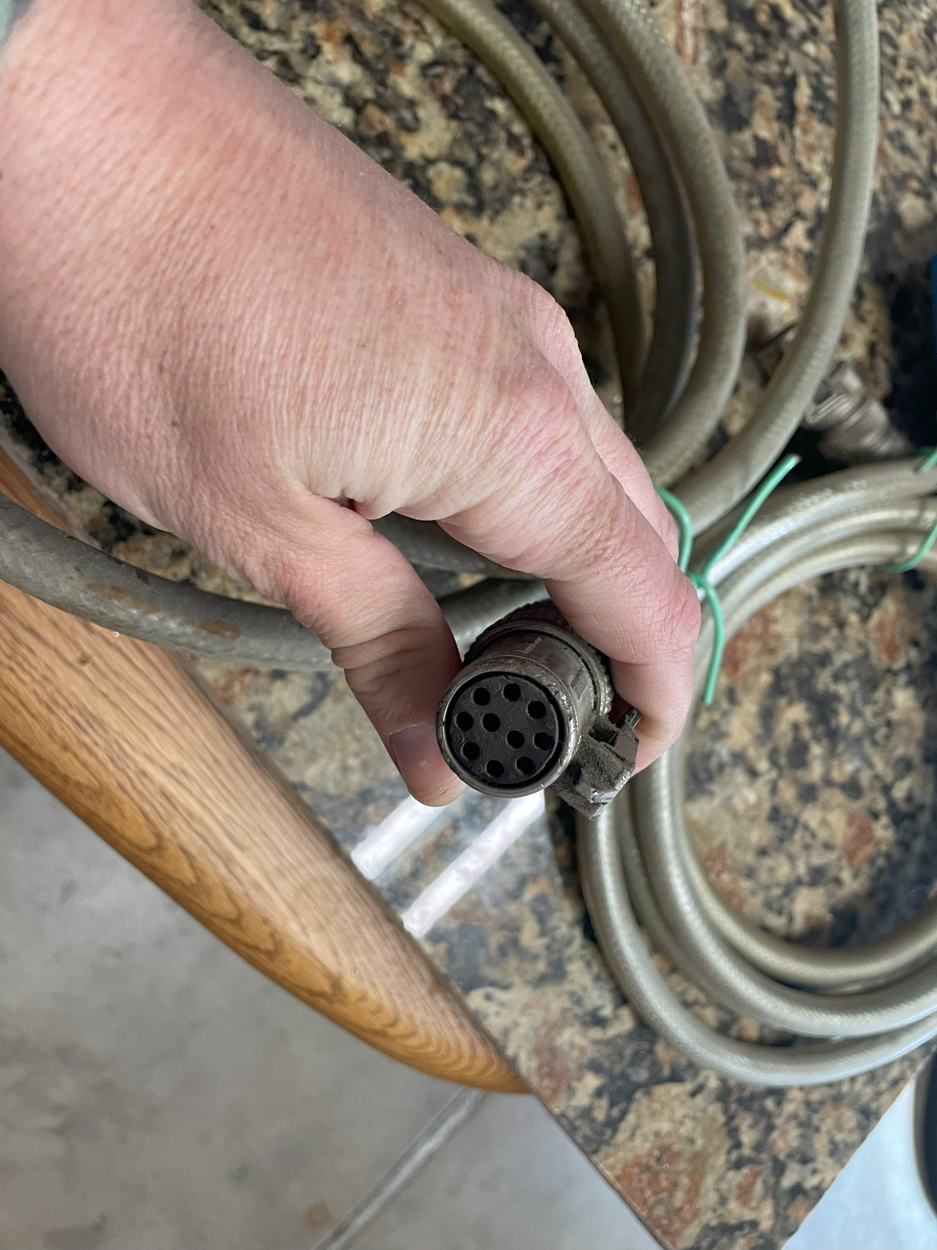
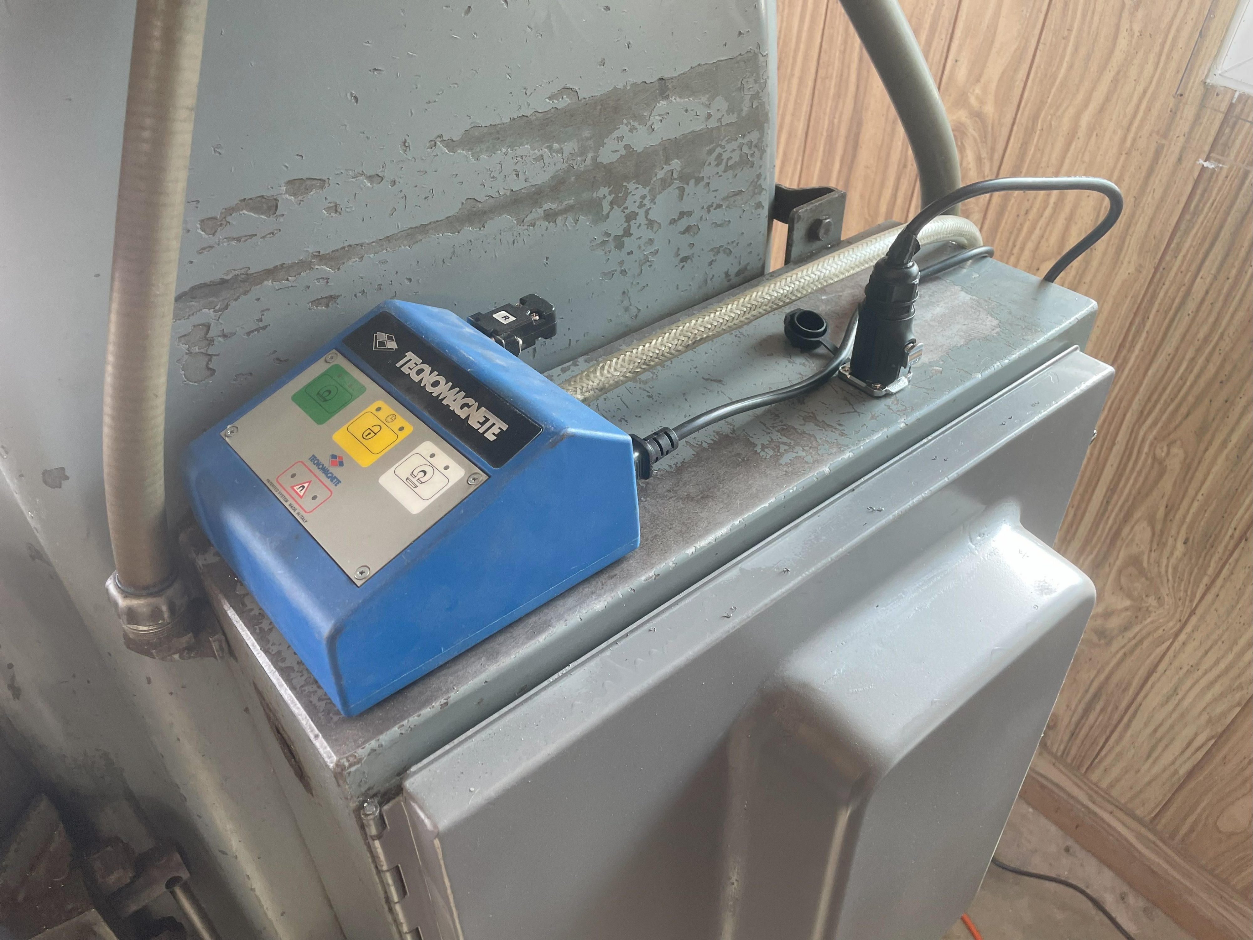
Here’s the problem: the Tecnomagnete QX303UMK6 EPM (Electro-Permanent Magnet) chuck has a 7-pin receptacle. It’s label says it works with ST100 controllers. But Tecnomagnete revised the ST100 and gave it a 10-pin plug on the discharge cable. In my case, the controller is an ST120F.

So how do you connect the two?
There is zero information online and I was really frustrated by that, so I’m writing this up to explain my solution.
The Easy Solution
If you have the money to spare (around $300), you can simply by an adapter from Tecnomagnete. It looks like this:
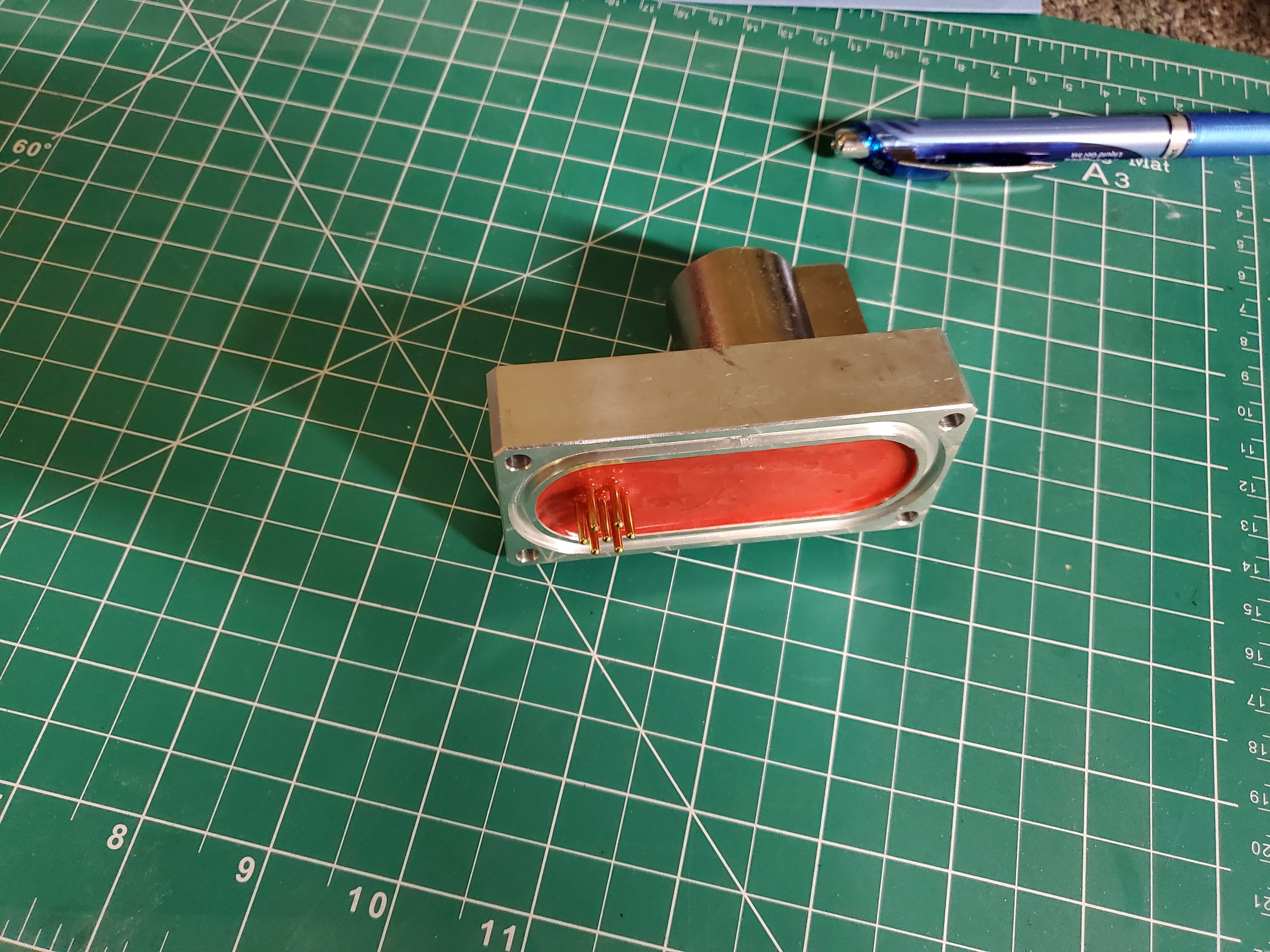

You remove the original receptacle and put on the new one that has 10 pins. Easy!
Useful Information
Fortunately for cheap people like myself, Tecnomagnete support is very helpful and they were able to get back to me with some really useful information.
They sent me wiring diagrams, pinouts, and schematics, which I was able to use to come up with my own inexpensive solution.
I really want to shout out Tecnomagnete’s support, because they went above and beyond to help. This is an old product line and they aren’t making money from it any more, but they genuinely did their best to assist me and that is something to applaud.
Connectors and Plugs
With the wiring information, the best solution would be to order a plug that matches the receptacle on the chuck and put that on the discharge cable.
However, it seems that it isn’t in production anymore and is impossible to find. I spent many hours searching, but couldn’t even find something similar enough to adapt to the purpose. Very annoying…
Therefore, if you don’t want to spend the money on Tecnomagnete’s adapter, you’re going to have to get hacky.
The Hacky Solution
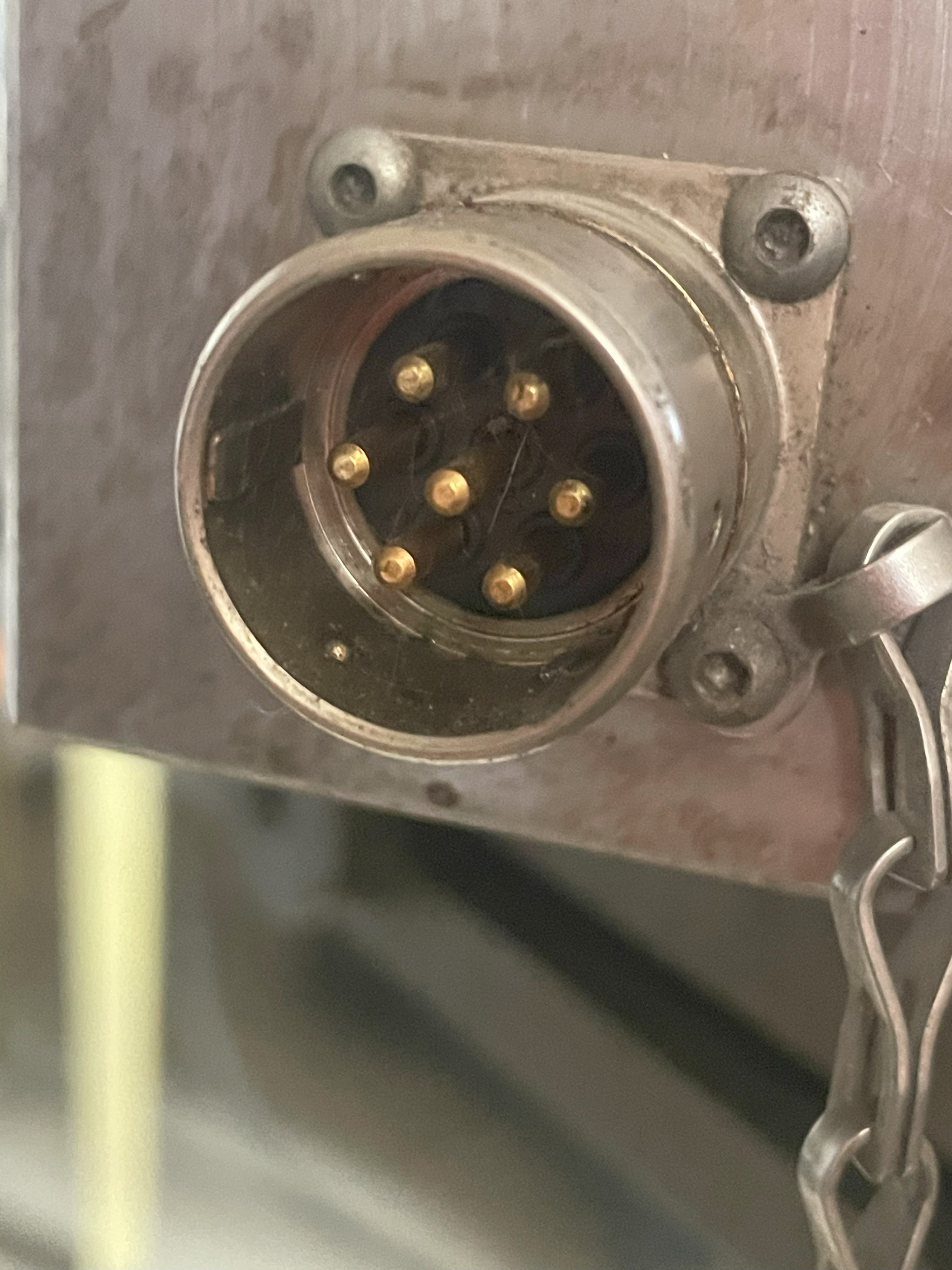
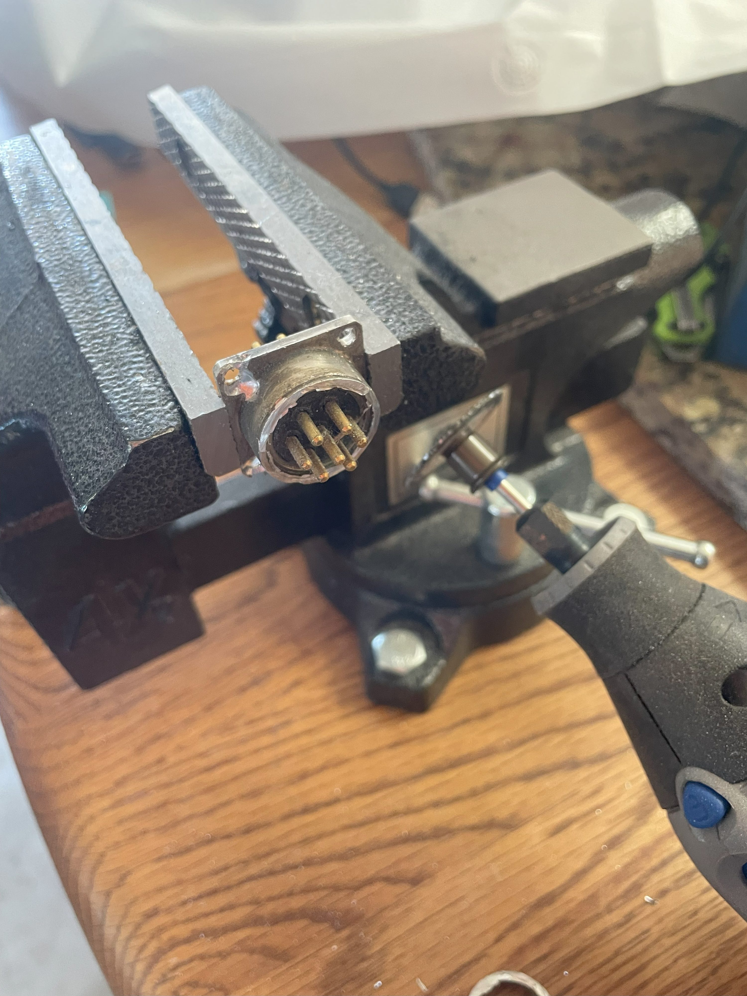
Alright, so my cheapskate solution relies on an interesting design choice of the chuck itself: the receptacle on the exterior is actually a kind of adapter itself, which plugs into another receptacle inside.
disclaimer: I’m not responsible for the damage you do from here on out.
To start, drill out the heads of the “rivets” holding the receptacle onto the Tecnomagnete body. Those are actually M3 screws, not rivets, but the heads are drilled or something and you can’t simply unscrew them.
With those drilled out, you can pull out the receptacle. MARK WHICH SIDE GOES UP! It should be pins 1 and 2 on top. You’ll see that there is an interior receptacle.
What we’re going to do is turn the original receptacle into a plug, which we can insert and remove from the interior receptacle.
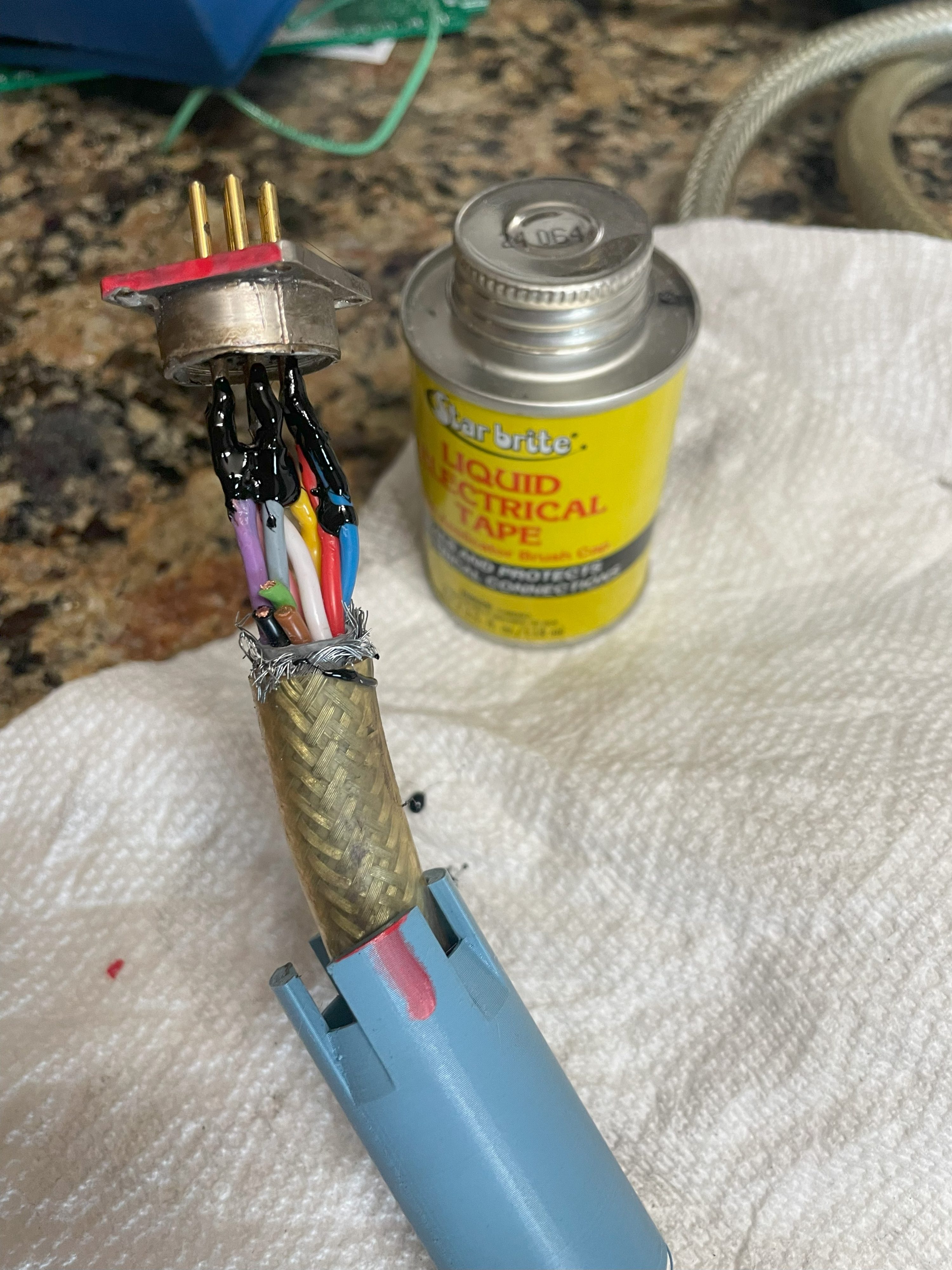
Cut the plug off the discharge cable on the controller and strip some of the wires.
While you’re working on this, you can 3D-print the sheath I designed.
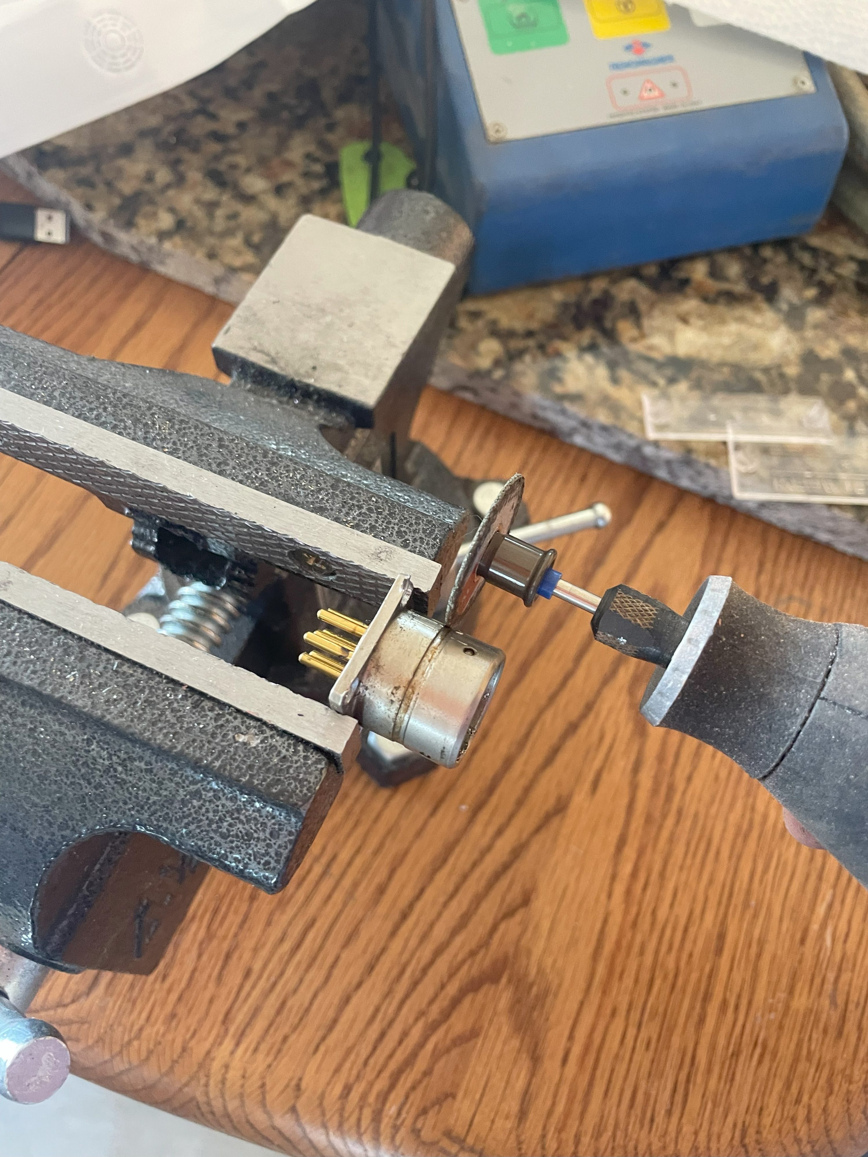
Then trim off some of the receptacle’s housing to expose the pins using a Dremel.
Now slip the 3D-printed sheath over the discharge cable and solder the discharge wires to the pins on the receptacle:
Terminal 1: 12 Wire - Pink (COM)   -->  Pin 7
Terminal 2: 10 Wire - White (CH 1) -->  Pin 5
Terminal 3: 13 Wire - Blue (COM)   -->  Pin 3
Terminal 4: 11 Wire - Red (CH 2)   -->  Pin 4
Terminal 5: 22 Wire - Brown (COM)  -->  NC
Terminal 6: 20 Wire - Gray (CH 3)  -->  Pin 2
Terminal 7: 23 Wire - Black (COM)  -->  NC
Terminal 8: 21 Wire - Violet (CH4) -->  Pin 1
Ground:     PE Wire - Yellow (PE)  -->  Pin 6 (center)
As you can see, some of the wires simple aren’t connected (marked “NC”). That includes green, which isn’t connected on the 10-pin connector, either. You can simply cut off brown, black, and green.
The reason this is okay is because the chuck shares the COM connections between channels.
After soldering, you can use some liquid electrical tape to protect the connections.
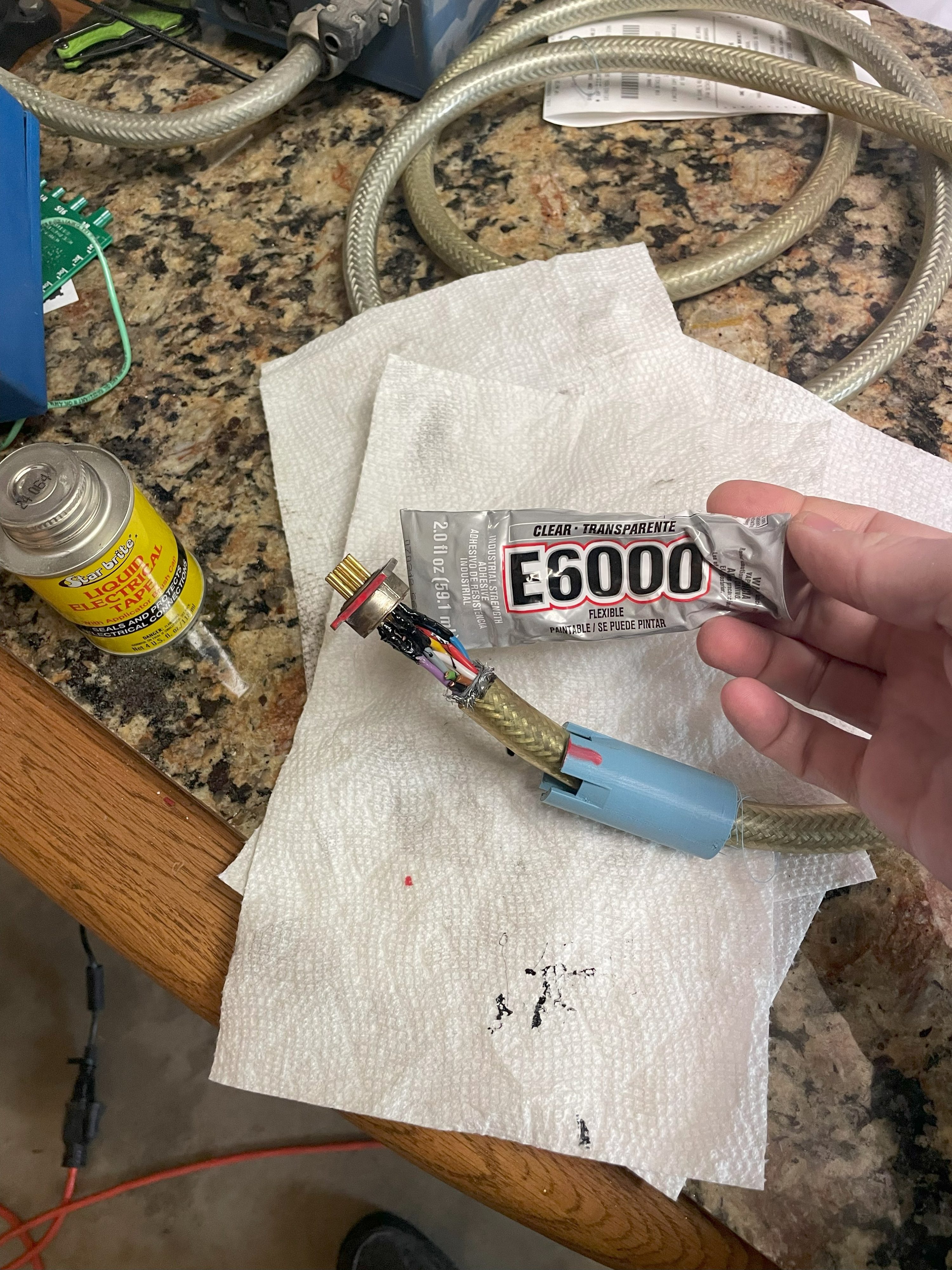
Make sure to mark the chuck, cable, and what is now the “plug” so you know the correction orientation.
Then use some glue (I used E600) to secure the 3D-printed shroud to both the cable and the plug (originally receptacle) housing. That is to prevent strain on the solder joints.
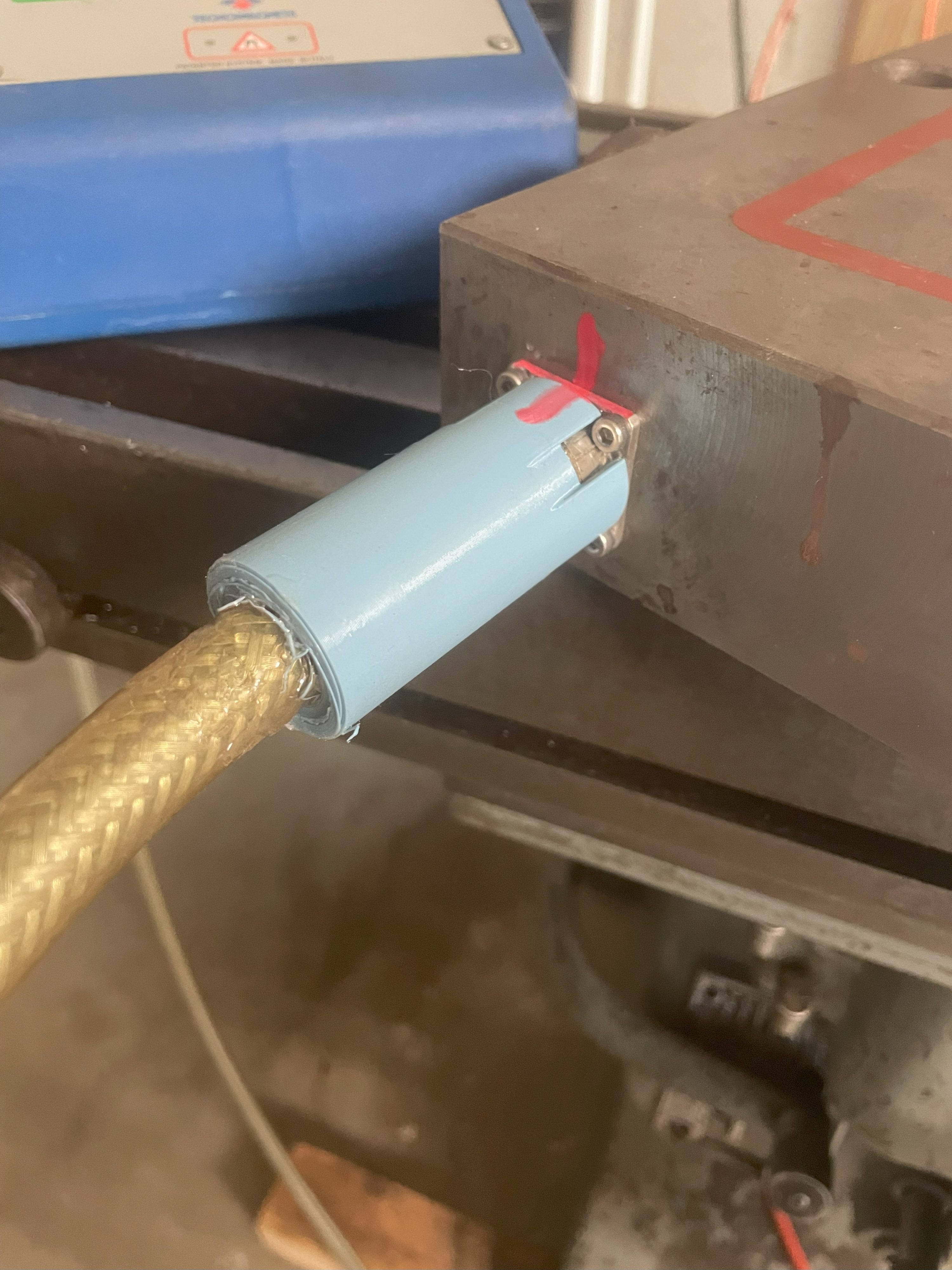
Finally, you can connect your new “plug” to the chuck. Use four M3x6mm screws to secure it.
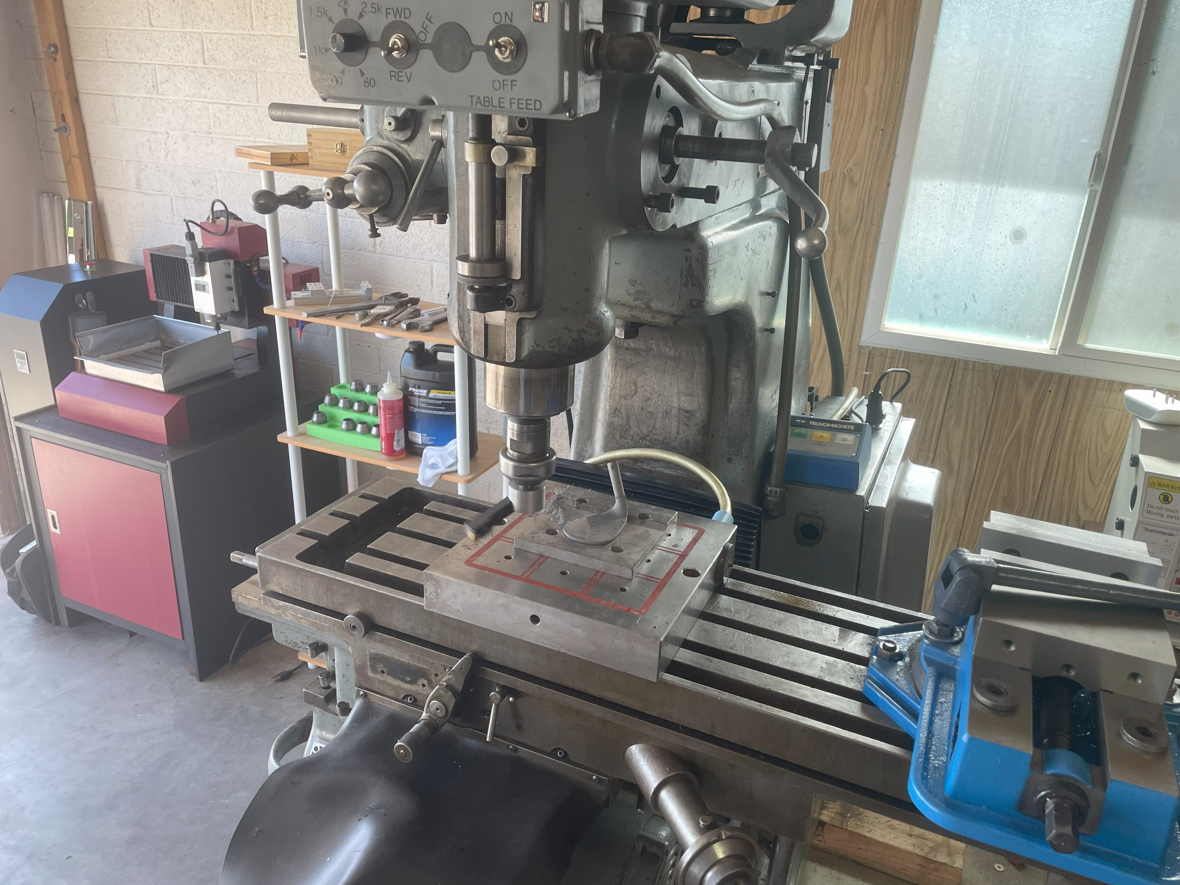
That’s it! The chuck should now work. Here’s a photo of a golf club I faced using the chuck:
P.S. you have to hold down the yellow “lock” button when you press either the magnetize or demagnetize button.
Leave a Reply